Friday 25th April 2025
My RC F-35 Project - by Toby Hewitt
Press Enter to search or ESC to close
Friday 25th April 2025
The past six months, I’ve been working on an ambitious project to create a functional RC F-35 model plane from scratch. While I have mostly succeeded, there have been a few setbacks and challenges along the way. My goal was to create a lightweight, operational model capable of flight, featuring retractable landing gear and the ability to transition from VTOL flight (vertical take-off and landing, similar to the British Harrier jet) to forward flight.
My inspiration for this came from a blend of one of my previous projects, a custom FPV drone, which sparked my interest with flying models and the technology behind them, as well as my personal interest in RC models. A few years ago, I had considered building a model similar to the F-35, but I had deemed it too difficult at the time, so I shelved the idea for me to revisit it in the future. More recently I saw a video on a VTOL Harrier, which reminded me of my previous idea. I was fascinated by the challenge of creating an RC plane from scratch and thanks to the knowledge I gained from my previous drone project, I felt much more confident to attempt it.
I was particularly interested in the VTOL transition and the Three Bearing Swivel Module (3BSM), the component at the rear of the plane that redirects the thrust from the main engine. It either directs the thrust straight out the back for forward flight or, in combination with the secondary fan closer to the front, redirects the air downwards by physically rotating the nozzle to be pointing towards the ground.
To provide an overview of the project, I’ll divide it into three main parts: the frame and main construction, avionics / flight software, and general electronics.
Frame and main construction
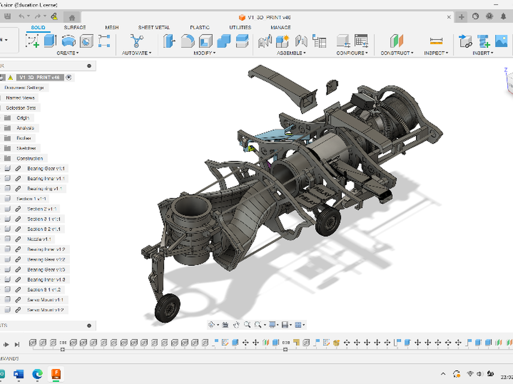
When I first started designing the F-35 on my CAD software (Fusion 360, which I had learnt through design technology engineering lessons), I knew I wanted a laser-cut frame. However, since I didn’t have access to a laser cutter at the time, I opted to build a simpler 3D-printed frame first to better understand the structure. After conducting some research, I decided to use two 70 mm EDFs (electric ducted fans) to power the plane. I imported 3D models of the EDFs and a low-poly model of the plane into Fusion 360 and I designed a few basic ribs following the shape of the low-poly model to get a sense of the desired scale. I decided on a length of just over one metre, as it fit the scale of the EDFs. However, in hindsight, the final weight of the plane was around 3 kg, while the combined maximum thrust of the motors was about 4.5 kg, so perhaps I should have reduced the size to lower the weight.
After a few weeks of prototyping, I had a working frame, but there were several issues. The most significant problem was that when the motors were turned on, the frame began to flex, causing instability in the air. I made various tweaks to address the minor issues, but it was not enough to eliminate the bending entirely. I realised that the next step was to switch to a much lighter laser-cut frame.
Frame and main construction
When I first started designing the F-35 on my CAD software (Fusion 360, which I had learnt through design technology engineering lessons), I knew I wanted a laser-cut frame. However, since I didn’t have access to a laser cutter at the time, I opted to build a simpler 3D-printed frame first to better understand the structure. After conducting some research, I decided to use two 70 mm EDFs (electric ducted fans) to power the plane. I imported 3D models of the EDFs and a low-poly model of the plane into Fusion 360 and I designed a few basic ribs following the shape of the low-poly model to get a sense of the desired scale. I decided on a length of just over one metre, as it fit the scale of the EDFs. However, in hindsight, the final weight of the plane was around 3 kg, while the combined maximum thrust of the motors was about 4.5 kg, so perhaps I should have reduced the size to lower the weight.
After a few weeks of prototyping, I had a working frame, but there were several issues. The most significant problem was that when the motors were turned on, the frame began to flex, causing instability in the air. I made various tweaks to address the minor issues, but it was not enough to eliminate the bending entirely. I realised that the next step was to switch to a much lighter laser-cut frame.
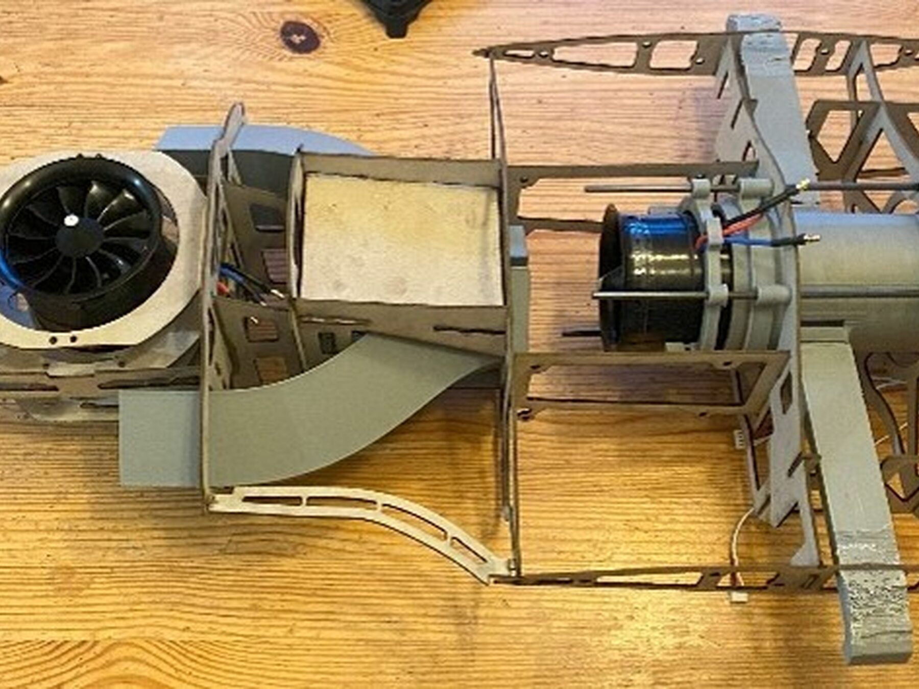
I reached out to Mr. Newton in the design technology engineering department, and he agreed to help cut the frame using the school’s laser cutter. Over the next few weeks, I redesigned the frame to work with 3 mm basswood. However, after being ready to cut the first iteration, I discovered that the wood I had purchased was actually closer to 2.7 mm thick rather than the advertised 3 mm. This required multiple test cuts to refine the tolerances of the joints and the holes for the carbon fibre tubes and screws. After finalising the first iteration with the new tolerances, Mr. Newton cut the frame from card to check everything before moving on to the basswood.
From the card model, I identified several minor issues, such as having incorrect tolerances for the servos to be mounted in. After resolving these, we proceeded with cutting the main frame in basswood just before the Christmas holidays of 2024.
During the first few weeks of the holidays, I installed all the electronics and did various tests. In doing so, I discovered that the warping issue from the old frame had returned. To address this, I redesigned the frame again, incorporating stronger braces to try and minimise bending. For Christmas, I received a small laser cutter, which allowed me to cut out and refine the redesigned components at home. Once the frame had stopped bending, I only made a few minor adjustments, leading to its current design.
Avionics / software
For the avionics of the plane, I used similar electronics to those in my drone, though some were more specialised for RC planes. The flight controller I chose was the SpeedyBee F405 WING, which serves as the brain of the aircraft. It stabilises and helps to control the plane using various sensors. I selected this controller primarily due to the number of servo outputs it has, all of which were necessary for my design.
To be able to control the plane, I used a Radiomaster RP1 ELRS receiver in combination with the Jumper T-Lite radio. This setup provides a range of a few hundred metres, which should be large enough for my needs. If I require a larger range in the future, I can add a stronger antenna.
The plane is powered by a 6S 4500mAh lithium polymer battery and two 70 mm 2300Kv EDFs, controlled by two 80A ESCs. These motors generate around 4.5 kg of thrust, which is enough to lift the plane off the ground in VTOL mode. For the software, I am currently using INAV but I plan to move to ArduPilot in the future as it has better compatibility with my motor setup and VTOL planes in general.
Electronics
The electronics system for the rest of the plane primarily consists of servos (motors) for the control surfaces and landing gear, along with a handful of custom PCBs (printed circuit boards) that help control the 3BSM at the rear of the plane. For control during flight, I have two servos for the ailerons (one in each wing for roll), two for the rudders (yaw control) and two for the elevators (pitch control). Also, I have one per landing gear to raise and lower the wheels.
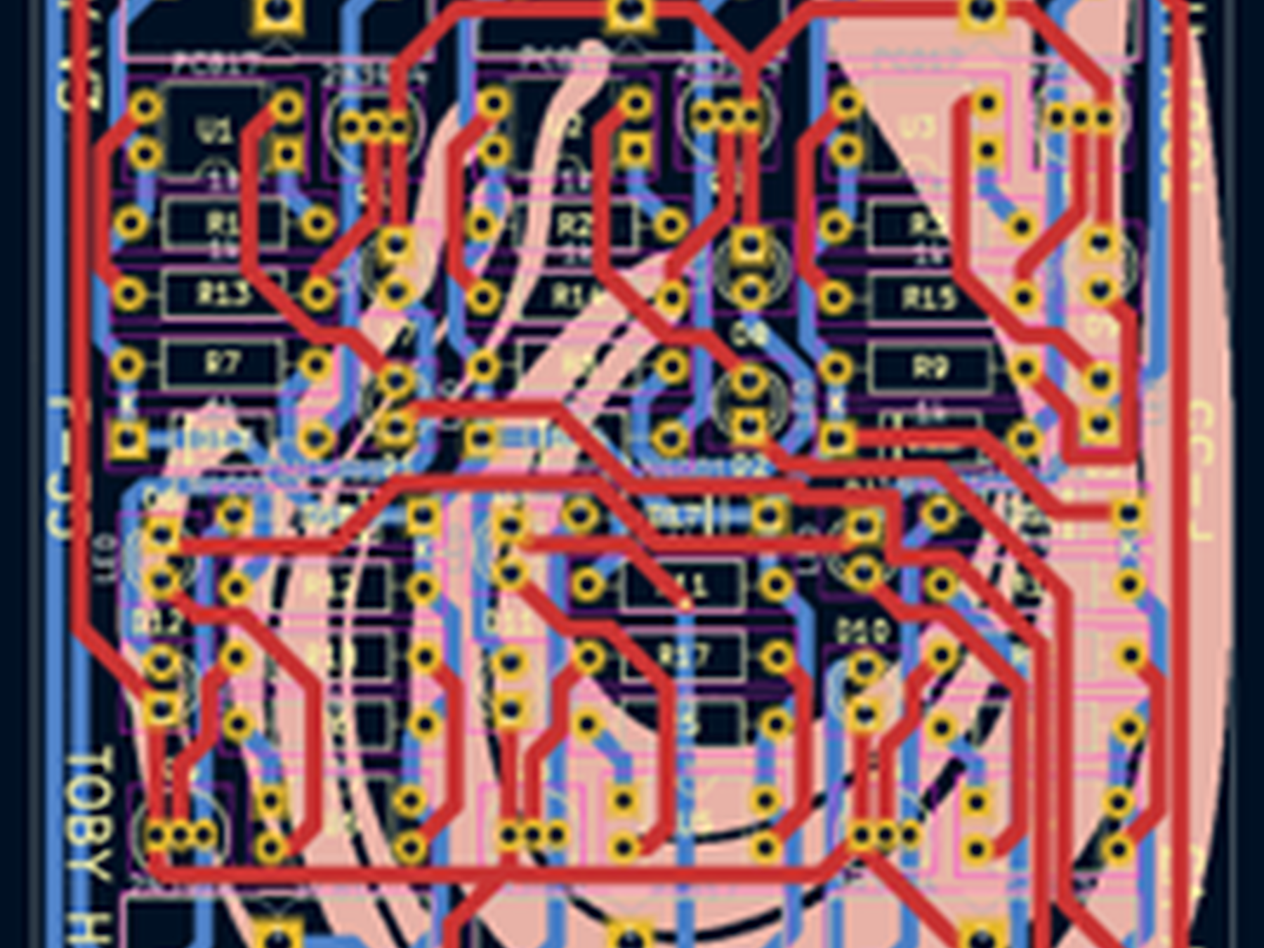
Since the 3BSM servos required an unconventional control method, I had to design a custom circuit. I couldn’t directly control the two servos the way I needed to from the flight controller since they had to be continuous rotation servos due to needing them to rotate through more than 180 degrees. While this was a good starting point, it wasn’t sufficient – I needed them to stop precisely once they rotated to a specific position (e.g. when the 3BSM was pointing downward).
To achieve this, I first prototyped a circuit on a breadboard using relays and physical limit switches. The servos would continue running until they hit a switch, cutting power to stop them in the correct position. Then when I flipped a switch on my radio, the power was restored, and the servos would reverse direction until they reached the opposite limit switch. Once I had a working prototype, I moved on to KiCad (a PCB design software) to create custom PCBs for the system. It took a few iterations to produce a reliable board, but once complete, I soldered a second one and installed both onto the frame.
Current status and next steps
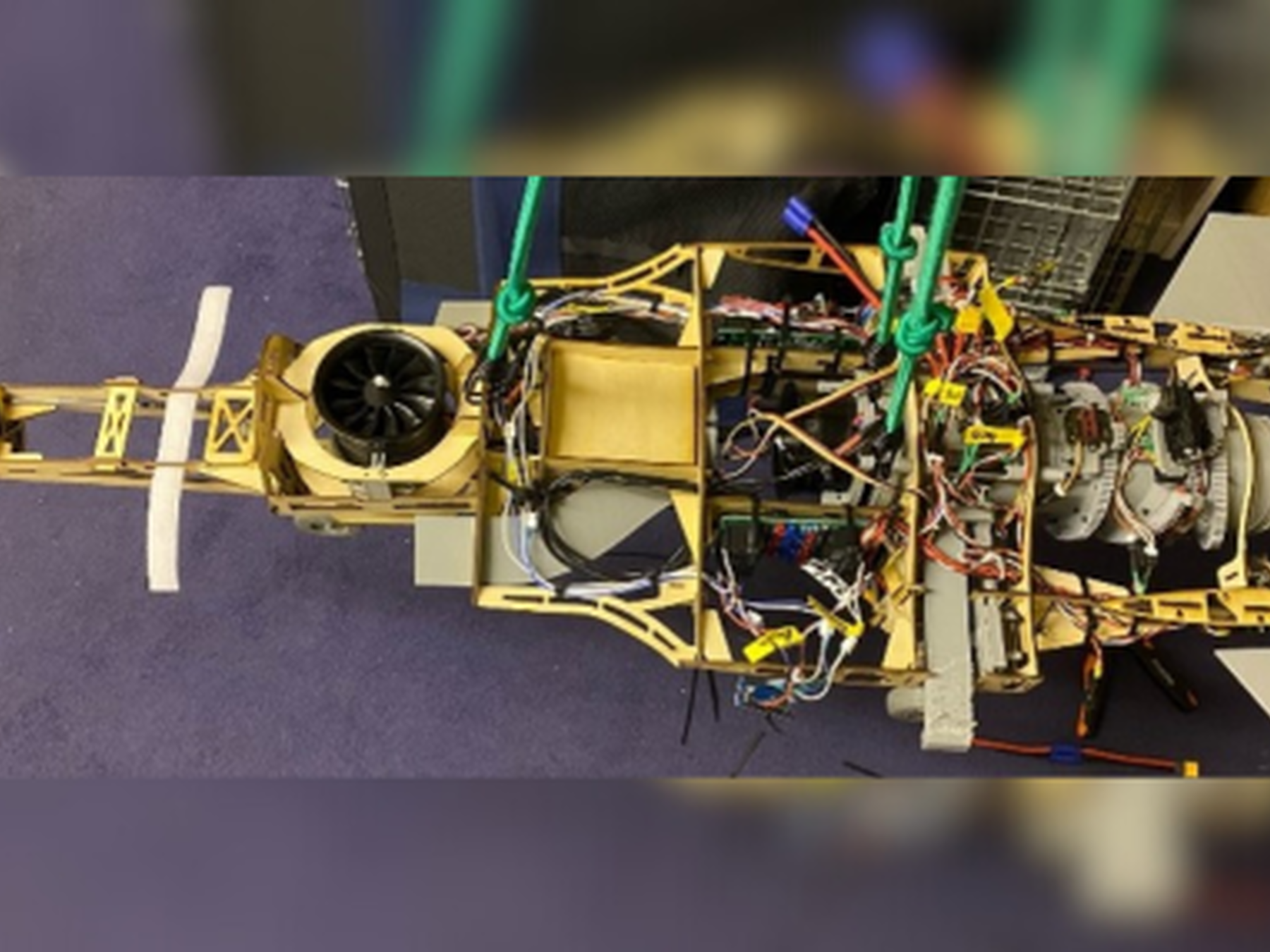
While I have not yet completed many flight tests, I have a plan for when I am ready. I will first create a wooden test frame and attach the plane to it via bungee cords so that I can do static VTOL tests. This keeps the plane secure while I tune the settings and protects it in case anything goes wrong. Once I am happy with its performance here, I will remove the test frame and hover the plane to check the stability of the VTOL mode off the test frame. I will then progress to testing the transition between the flight modes, as I fear this could be the most challenging part to get right as the transition requires precise control to keep the plane stable.
If these tests are successful, I plan to move on to forward flight and testing things such as how well it controls at different speeds and the maximum speed it can reach. I will take the data from the test to adjust the rates further to improve the plane and make it easier to control during flight.
In conclusion, my RC F-35 project has involved significant challenges, from designing a laser-cut frame to using specialised electronics and software. Although the plane is not yet flight-ready, I have made substantial progress towards my goals, especially in terms of the structural design and avionics setup. The next steps involve finalising the frame and conducting a series of flight tests to ensure everything works as planned. Throughout the project, I have learnt lots and I’m looking forward to the future of the plane and seeing how it performs in the air.
Blog posts are on various subjects; sport, drama, art or CCF just to name a few. Our students are encouraged to write about what interests them, as well as the community.